
In the realm of engineering and manufacturing, precision is not simply a desirable feature — it is an absolute necessity. The success of modern machines, automotive components, aerospace structures, and even medical devices depends on how accurately each part is made and measured. One of the most trusted tools that stands as the guardian of accuracy in this process is the micrometer. Known for its ability to measure components with extreme precision, often to the nearest thousandth of a millimeter, the micrometer is an essential instrument that bridges the gap between design intent and physical reality.
This comprehensive article explores the world of micrometers in depth — from their origin and design principles to their types, usage, calibration, and importance in modern manufacturing. It also discusses the technological advancements that are reshaping how micrometers function today, making them integral tools in industries that demand exceptional precision.
1. Understanding the Micrometer: The Principle of Precision
The micrometer, often called a micrometer screw gauge, is a mechanical measuring instrument designed to measure small distances, thicknesses, and diameters with a very high level of accuracy. It operates on the principle of a screw thread, which converts small rotational movements into precise linear movements.
At the heart of a micrometer is a finely threaded spindle that advances or retracts when the thimble is turned. The pitch of this screw determines the instrument’s sensitivity — that is, how much linear movement occurs per revolution of the screw. Because of this finely calibrated screw mechanism, micrometers can measure with a precision that surpasses most other manual measuring tools such as calipers.
| Parameter | Typical Micrometer Value | Explanation |
|---|---|---|
| Screw Pitch | 0.5 mm per revolution | Determines how far spindle moves with one full turn |
| Least Count | 0.01 mm (mechanical) or 0.001 mm (digital) | Smallest measurement readable |
| Measuring Range | 0–25 mm, 25–50 mm, 50–75 mm, etc. | Depends on micrometer size |
| Accuracy | ±0.002 mm or better | Measurement deviation allowed |
This simple yet effective mechanical principle allows engineers to perform highly accurate dimensional measurements that form the basis of quality control and part interchangeability in industrial manufacturing.
2. Historical Development of the Micrometer
The concept of the micrometer dates back to the 17th century, with its invention credited to William Gascoigne, who used a screw-based measuring device in astronomical telescopes to measure angular distances. However, it was Jean Laurent Palmer in 1848 who developed the handheld version of the micrometer screw gauge that laid the foundation for modern designs.
As the industrial revolution gained pace, the need for precision tools became increasingly evident. Machine parts, steam engines, and precision instruments demanded accuracy that human senses could not ensure. The micrometer evolved as a result, becoming a symbol of industrial accuracy and engineering excellence.
By the 20th century, the micrometer became a staple in workshops, machine shops, and laboratories, where its ability to verify tolerances within microns made it indispensable. Modern micrometers have since incorporated digital displays, ratchet stops, carbide measuring faces, and data output ports, transforming from purely mechanical devices into hybrid instruments of precision and technology.
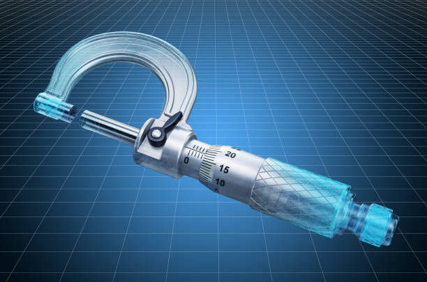
3. Construction and Working Mechanism
A standard micrometer consists of several essential parts, each contributing to its precise operation. Understanding its construction provides clarity on why this instrument remains unparalleled in accuracy.
| Part Name | Function |
|---|---|
| Frame | The rigid C-shaped body that holds the anvil and barrel in place, ensuring stability. |
| Anvil | The fixed measuring surface against which the object rests. |
| Spindle | A movable measuring face that advances or retracts to contact the object being measured. |
| Sleeve (or Barrel) | The stationary scale engraved with millimeter markings. |
| Thimble | The rotating part with fine graduations that moves the spindle precisely. |
| Ratchet Stop | Prevents over-tightening by ensuring consistent measuring pressure. |
| Lock Nut | Locks the spindle in position for consistent readings. |
When the thimble is turned, the spindle moves in or out through a precisely cut screw mechanism. Each complete rotation of the thimble translates into a known linear displacement of the spindle. By reading the combined markings on the sleeve and thimble, a user can determine the exact dimension of the measured component.
Mechanical micrometers require manual reading of scales, while digital micrometers feature an LCD display that automatically shows the dimension, minimizing human reading errors.
4. Types of Micrometers in Engineering Applications
Micrometers come in various types, each designed to measure specific features of components. Below are the most commonly used categories in engineering and manufacturing:
a. Outside Micrometer
This is the most common type, used to measure the outside diameter or thickness of a component such as shafts, wires, or sheets. It provides accuracy typically up to ±0.002 mm.
b. Inside Micrometer
Designed to measure the internal diameter of holes, pipes, or cylinders. It uses extensions to reach different diameters.
c. Depth Micrometer
This type measures the depth of slots, holes, or steps. It consists of a flat base that rests on the reference surface and a spindle that extends downward into the cavity.
d. Screw Thread Micrometer
Used to measure the pitch diameter of screw threads with interchangeable anvils shaped to fit thread flanks accurately.
e. Digital Micrometer
Integrates electronic sensors and LCD displays for easy reading. Some models offer data output capabilities for integration with quality control software.
f. Tube Micrometer
Specially designed with a ball-shaped anvil to measure tube wall thickness without damaging the surface.
5. Reading a Micrometer: Step-by-Step Process
Although digital micrometers simplify reading, mechanical versions require users to interpret scale readings manually. The following steps outline how to read a standard metric micrometer with a least count of 0.01 mm:
- Note the main scale reading on the sleeve (in millimeters).
- Add the thimble reading (each division typically equals 0.01 mm).
- Sum both values to get the final measurement.
- Use the ratchet stop to ensure consistent contact pressure, avoiding parallax or compression errors.
For example, if the main scale shows 5.5 mm and the thimble shows 28 divisions, then the total reading is:
5.5 + (28 × 0.01) = 5.78 mm
This method ensures precise readings when measuring small dimensions critical to component performance.
6. Calibration and Accuracy Maintenance
The reliability of a micrometer depends on regular calibration and careful handling. Over time, continuous use can lead to mechanical wear or thermal distortion, both of which affect accuracy.
Calibration steps generally include:
- Visual Inspection: Check for dirt, burrs, or damage on the anvil and spindle faces.
- Zero Adjustment: Close the spindle gently and verify the zero mark alignment; adjust if necessary.
- Gauge Block Verification: Use certified gauge blocks to confirm readings at multiple points within the measuring range.
- Environmental Control: Perform calibration in a temperature-controlled environment, ideally around 20°C, to minimize thermal expansion effects.
Common sources of error include: temperature changes, incorrect measuring pressure, worn threads, or foreign particles on measuring faces. Proper storage, cleaning, and use of the ratchet stop greatly enhance the tool’s lifespan and reliability.
7. Comparison Between Micrometer and Vernier Caliper
Both micrometers and vernier calipers are precision measuring tools used in engineering workshops. However, they serve slightly different roles in measurement accuracy and usability.
| Feature | Micrometer | Vernier Caliper |
|---|---|---|
| Accuracy | ±0.002 mm | ±0.02 mm |
| Least Count | 0.01 mm (mechanical) or 0.001 mm (digital) | 0.02 mm (mechanical) |
| Range | Limited (25 mm per instrument) | Wide (up to 300 mm or more) |
| Operation | Screw-based | Sliding scale |
| Ease of Use | Slower but more precise | Faster but slightly less accurate |
| Applications | High-precision tasks | General measurements |
In short, micrometers are preferred when absolute precision is required, while vernier calipers are used for broader measurements or quick checks.
8. Applications of Micrometers in Modern Industries
The micrometer’s applications span nearly every engineering and manufacturing field. Its role extends far beyond dimensional verification — it ensures that every part functions as intended within permissible tolerances.
a. Mechanical Engineering:
Used for checking shafts, bearings, and machine components to ensure perfect fits and alignments.
b. Automotive Industry:
Essential in quality control for measuring pistons, crankshafts, valves, and other engine components that operate under tight tolerances.
c. Aerospace Manufacturing:
Aircraft components demand exceptional accuracy; micrometers are vital in verifying turbine blades, airframe parts, and hydraulic fittings.
d. Precision Tooling:
In tool and die making, micrometers confirm the exact dimensions of molds, jigs, and fixtures that define production accuracy.
e. Metalworking and Machining:
Used to verify part thickness, diameter, and surface consistency after turning, milling, or grinding operations.
f. Electronics and Semiconductor Manufacturing:
Micrometers are applied for measuring micro-scale mechanical parts, connectors, and casings that require sub-millimeter accuracy.
9. The Importance of Precision in Manufacturing
Manufacturing depends heavily on maintaining consistent dimensions. Even a slight deviation of a few microns can cause component failure, reduce lifespan, or create inefficiencies. The micro-meter allows engineers to monitor and control these deviations.
Consider this example:
| Component | Tolerance Range (mm) | Allowable Deviation (µm) |
|---|---|---|
| Automotive piston | 0.001 – 0.003 | ±2 µm |
| Bearing journal | 0.002 – 0.004 | ±3 µm |
| Aerospace turbine blade | 0.0005 – 0.001 | ±1 µm |
Such minuscule tolerances can only be verified with precision tools like micro-meters. Without them, the production of modern machines, engines, or aerospace parts would be nearly impossible.
10. Digital and Smart Micrometers: The Modern Evolution
While traditional micro-meters rely purely on mechanical scales, the advent of digital technology has revolutionized measurement systems. Digital micro-meters incorporate electronic sensors that translate spindle movement into numerical readings displayed instantly on an LCD screen.
Advantages of digital micrometers include:
- Higher readability: Eliminates human reading error.
- Data output ports: Connect to computers for real-time statistical process control.
- Zero setting: Allows easy measurement of relative dimensions.
- Conversion capability: Switch between metric and imperial units.
- Storage memory: Saves previous measurements for comparative analysis.
Modern “smart micro-meters” can even connect via Bluetooth or USB interfaces to transmit measurement data directly to inspection software, allowing real-time monitoring and improved quality assurance.
This evolution represents a fusion of mechanical reliability and digital convenience — a crucial advancement for Industry 4.0, where automation and data-driven decisions dominate production lines.
11. Micrometer Care and Best Practices
A micro-meter, though durable, requires careful handling and maintenance. Negligence can quickly lead to loss of accuracy.
Best Practices for Micrometer Maintenance:
- Clean before and after use: Remove dust and oil to prevent wear.
- Avoid dropping: The precision thread and measuring faces can deform easily.
- Store in protective cases: Prevent exposure to temperature extremes and humidity.
- Check zero reading frequently: Especially before critical measurements.
- Use proper measuring pressure: Apply consistent force via the ratchet stop.
- Periodic calibration: Recommended every six months for industrial use.
A well-maintained micro-meter can last decades while retaining its original accuracy, proving its long-term value in manufacturing environments.
12. Challenges and Limitations
Despite their strengths, micro-meters have a few limitations:
- Limited range: Each micro-meter covers only 25 mm of measurement, requiring multiple instruments for larger dimensions.
- Sensitivity to environment: Temperature and dirt can affect accuracy.
- User dependency: Manual micro-meters demand skill and patience to achieve consistent results.
- Cost: High-quality micro-meters, especially digital ones, can be expensive but justify their cost through precision and longevity.
Manufacturers often overcome these challenges through automation, regular calibration, and training operators on precision measurement techniques.
13. The Future of Micrometry in Engineering
The future of micro-meters is being shaped by digital integration, nanotechnology, and smart manufacturing systems.
Emerging micro-meters now feature wireless connectivity, AI-based error compensation, and self-calibration capabilities. In advanced industries such as semiconductor manufacturing or aerospace engineering, non-contact optical micro-meters are being developed, capable of measuring micro and nano-level features without physical touch — an essential evolution where even a few microns of contact pressure can distort readings.
Future innovations may include:
- 3D micrometers capable of capturing geometric data instead of single dimensions.
- Nano-micrometers for sub-micron resolution in scientific research.
- Augmented reality integration for visual guidance during measurements.
As manufacturing continues to evolve toward smart factories and precision robotics, the humble micro-meter will continue to play a critical role — not as an outdated tool, but as a foundation upon which future accuracy is built.
14. Conclusion
The micro-meter remains one of the most respected and indispensable tools in the world of engineering and manufacturing. Its evolution from a purely mechanical screw gauge to a digital precision instrument highlights how even the simplest concepts can continue to advance through innovation.
By enabling measurements within microns, micro-meters ensure that every manufactured part meets design specifications, performs reliably, and integrates seamlessly with other components. From the roaring engines of automobiles to the delicate mechanisms of aerospace systems, this small instrument silently ensures perfection.
In an era dominated by technology and automation, precision measurement will always be the cornerstone of progress. The micro-meter — steadfast, reliable, and ever-evolving — stands as proof that even the smallest measurements can define the largest achievements in engineering.
Frequently Asked Questions (FAQs)
1. What is a micrometer used for in engineering?
A micrometer is used to measure small dimensions such as thickness, diameter, or length of components with high precision, ensuring manufacturing accuracy within microns.
2. How accurate is a micrometer compared to other tools?
Micrometers are significantly more accurate than calipers, offering precision typically within ±0.002 mm, making them suitable for high-precision applications like aerospace and automotive engineering.
3. How is a micrometer calibrated?
Calibration involves verifying measurements using gauge blocks, adjusting the zero point, and ensuring accuracy across the measuring range under controlled temperature conditions.
4. What are the main types of micrometers used in industry?
Common types include outside, inside, depth, screw thread, and digital micrometers, each designed for specific measurement tasks.
5. What is the future of micrometers in manufacturing?
The future lies in digital, wireless, and AI-assisted micrometers integrated with data systems for real-time monitoring, ensuring continuous improvement in manufacturing precision.