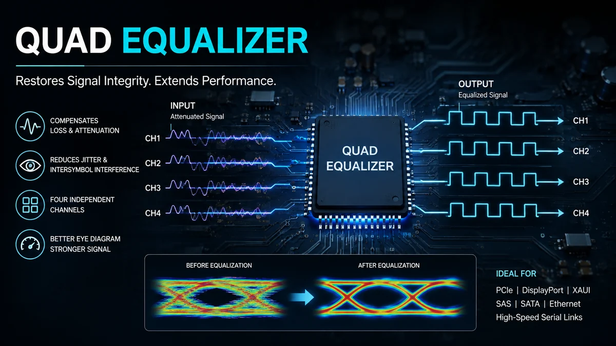
High-speed digital signals rarely arrive at a receiver exactly as they left the transmitter. PCB traces, backplanes, connectors, and copper cables introduce frequency-dependent loss that can distort pulses, increase jitter, and eventually make the receiver misread data.
A quad equalizer addresses this problem across four signal channels in a single device. Rather than simply increasing the entire signal level, it applies frequency-dependent compensation designed to counter losses introduced by the transmission medium. This makes quad equalizers useful in high-speed interfaces such as PCI Express, DisplayPort, XAUI, Ethernet-related links, SAS, SATA, and other serial communication systems.
Quick answer: A quad equalizer is a four-channel signal-conditioning device that compensates for high-frequency losses in PCB traces, backplanes, or cables. By restoring attenuated signal components and reducing intersymbol interference and deterministic jitter, it helps a high-speed receiver recover data more reliably over longer or more challenging interconnects.
What Is a quad equalizer?
The word quad refers to four channels. In high-speed digital electronics, those channels commonly carry differential serial data.
The equalizer portion performs the more important job: compensating for the unequal attenuation introduced by the physical transmission path.
Copper interconnects do not affect every frequency equally. As data rates rise, higher-frequency components tend to suffer greater attenuation. Long FR4 traces, connectors, vias, backplanes, and cables can therefore change the shape of the transmitted waveform.
A quad equalizer provides signal conditioning for four such channels in one integrated circuit.
For example, Analog Devices describes the MAX3980 as a four-lane equalizer for 3.125 Gbps NRZ data. It was designed to compensate for transmission-medium losses on XAUI links and support four differential lanes.
Texas Instruments’ DS32EV400 follows the same basic four-channel concept but targets operation up to 3.2 Gbps and provides programmable equalization for each channel.
So the term does not describe one specific chip or data rate. It describes an architectural category: four channels of equalization integrated into one device.
Why High-Speed Signals Need Equalization
At low speeds and short distances, a PCB trace can behave almost like an ordinary electrical connection. At multi-gigabit data rates, that assumption stops working.
The interconnect becomes part of the signal-integrity problem.
Frequency-dependent insertion loss
PCB materials and cables attenuate signal energy. Higher-frequency components can experience more loss than lower-frequency components, meaning a transmitted pulse does not maintain its original shape.
The problem generally becomes more difficult as one or more of these increase:
- data rate
- trace length
- cable length
- connector count
- PCB loss
- discontinuities in the signal path
Equalization attempts to compensate for this channel behavior rather than applying the same gain across the entire frequency spectrum.
Intersymbol interference
One important consequence of channel loss is intersymbol interference (ISI).
Ideally, each transmitted symbol occupies a clearly distinguishable time interval. When the channel spreads or distorts pulses, energy from one symbol can interfere with neighboring symbols.
The receiver then has less margin to distinguish ones from zeros.
Analog Devices specifically identifies reduction of intersymbol interference as one of the purposes of receiver equalization in its MAX3980 and MAX3981 devices.
Deterministic jitter
Channel distortion can also move signal transitions away from their ideal timing positions.
This contributes to deterministic jitter and reduces the available timing margin at the receiver.
Texas Instruments states that its DS32EV400 compensates for transmission-medium losses while reducing medium-induced deterministic jitter across four NRZ channels.
The practical objective is therefore not simply to produce a larger waveform. It is to recover a cleaner, more usable signal.
How Does a quad equalizer Work?
A simplified high-speed link looks like this:
Transmitter → PCB/Cable Channel → Equalizer → Receiver
The transmitter creates the original serial signal. As that signal passes through the channel, high-frequency content is attenuated and the waveform becomes increasingly distorted.
The equalizer provides a frequency response that compensates for part of this loss.
Step 1: Four differential signals enter the device
Many high-speed serial interfaces use differential signaling, where each lane consists of a pair of conductors.
A four-channel equalizer can process four such lanes simultaneously.
Depending on the device and interface, the inputs may support AC coupling, DC coupling, or both. The DS32EV400, for example, supports AC- or DC-coupled operation with a wide input common-mode range.
Step 2: The receiver equalization stage compensates for loss
The equalizer applies greater compensation where the channel has produced greater attenuation.
This can improve edge definition and reduce the effects of ISI.
The amount of compensation matters. Too little equalization leaves substantial channel loss uncorrected. Excessive equalization can amplify unwanted high-frequency noise and produce its own signal-integrity problems.
This is why many devices provide selectable or programmable equalization levels.
The DS32EV400 offers eight equalization levels configurable through control pins or an SMBus interface.
Step 3: The conditioned signal reaches the receiver
After compensation, the output should present a larger usable eye opening and better timing margin than the severely attenuated input signal.
The exact improvement depends on the equalizer, channel characteristics, data rate, PCB construction, cable, connectors, transmitter settings, and receiver.
Equalization is therefore best understood as channel-loss compensation, not a universal repair mechanism.
Equalizer vs. Redriver vs. Preemphasis
These terms are closely related but should not automatically be treated as synonyms.
| Technology | Main Function | Typical Position |
|---|---|---|
| Equalization | Compensates for channel loss | Receiver/input side |
| Redriver | Conditions and retransmits the signal | Within the signal path |
| Preemphasis/deemphasis | Shapes transmitter output for expected channel loss | Transmitter/output side |
| Retimer | Recovers data and clock timing before retransmission | Within the link |
Some ICs combine multiple functions.
The MAX14954, for example, is described as a quad equalizer/redriver. It provides programmable input equalization at the receiver along with programmable redrive circuitry. Its output stage can restore deemphasis lost across the PCB and compensate for board loss.
The MAX3987 combines four-channel receive equalization with programmable output preemphasis.
This distinction matters when diagnosing a design. A channel that primarily suffers frequency-dependent attenuation may benefit from equalization, while a system with a different signal-integrity limitation could require another form of conditioning.
Programmable and Adaptive Equalization
Not every physical channel has the same loss.
A short PCB trace may need relatively little compensation. A long backplane or cable can require substantially more.
That creates two common approaches.
Programmable equalization
A programmable equalizer allows the designer to select from multiple compensation settings.
This can be controlled through:
- hardware pins
- DIP switches on evaluation hardware
- SMBus
- I²C
- device registers
- software interfaces
The DS32EV400 uses eight programmable levels and allows settings through control pins or SMBus.
Programmability is useful when the approximate channel characteristics are known and the designer can test which setting produces the strongest signal-integrity margin.
Adaptive equalization
Adaptive designs can automatically adjust compensation according to the incoming channel.
The MAX3980, for example, was designed to adaptively support XAUI lanes across long FR4 PCB paths.
Adaptive behavior can simplify systems where channel loss varies, although implementation and capabilities depend heavily on the specific device.
Where quad equalizer Devices Are Used
Four-channel equalization has appeared across several generations of high-speed communication technology.
PCI Express
PCI Express is one notable application.
Older devices such as the MAX4950 were designed as quad PCIe equalizer/redrivers supporting first- and second-generation PCIe rates, while later MAX14950 and MAX14954 devices extended the concept to PCIe Gen III operation.
Historically, the DS50EV401 also targeted PCIe links at rates up to 8 Gbps and was designed to compensate for loss in PCB backplanes and cables.
DisplayPort
The DS32EV400 is categorized by Texas Instruments as a DisplayPort quad equalizer.
It supports four channels, operates up to 3.2 Gbps, and can equalize as much as 14 dB of loss at that rate according to TI’s specifications.
XAUI and 10-Gigabit Ethernet
XAUI uses multiple serial lanes and is another natural application for four-channel equalization.
The MAX3980 was designed for 3.125 Gbps XAUI links across FR4 PCB material. Analog Devices states that it can support up to 40 inches, or approximately one meter, of FR4.
The related MAX3981 targets four 3.125 Gbps XAUI lanes over twin-axial cable and specifies a reach of up to 10 meters.
Storage and other high-speed interfaces
The MAX3987 demonstrates how the same signal-conditioning principle can serve a wider group of protocols.
Its listed applications include:
- PCIe-compatible links
- XAUI and XAUI2
- Fibre Channel
- Interlaken
- InfiniBand
- SAS-2
- SATA Revision 3
- FR4 and cable equalization
It supports four channels and operation up to 8.5 Gbps.
Modern equalization technology has moved far beyond those data rates. Semtech’s GN8112, for instance, is a four-channel linear PAM4 equalizer designed for 56 GBaud/112 Gbps-per-channel copper-link applications.
That illustrates an important point: quad equalizer describes the channel architecture, not a fixed generation of high-speed technology.
Understanding NRZ, PAM4, and Equalization
Many traditional quad equalizers were designed around NRZ, or non-return-to-zero, signaling.
With NRZ, a symbol effectively represents one of two amplitude states. Devices such as the MAX3980 and DS32EV400 explicitly target NRZ data channels.
Modern ultra-high-speed links increasingly use PAM4, which carries information using four amplitude levels.
PAM4 increases the number of bits that can be represented per symbol but also reduces the voltage separation between adjacent levels. That makes signal integrity and equalization especially important.
Semtech’s GN8112 is an example of a quad linear PAM4 equalizer intended for high-speed copper links, including active copper cable applications.
The underlying objective remains familiar: compensate for channel loss sufficiently for the receiving system to interpret the transmitted data reliably.
What Specifications Matter When Evaluating a quad equalizer?
Choosing an equalizer based only on maximum data rate is a common mistake.
Several specifications need to be considered together.
Number of channels
A true quad device provides four channels.
Check whether those channels can be independently configured. Independent control can be valuable when the four physical routes have different losses.
Maximum supported data rate
The equalizer must support the signaling rate of the target interface.
Examples illustrate how widely this can vary:
| Device | Channels | Specified Speed/Use |
|---|---|---|
| MAX3980 | 4 | 3.125 Gbps XAUI |
| DS32EV400 | 4 | Up to 3.2 Gbps |
| MAX14954 | 4 | PCIe Gen I/II/III |
| MAX3987 | 4 | Up to 8.5 Gbps |
| DS64EV400 | 4 | Up to 10 Gbps |
| GN8112 | 4 | 56 GBaud / 112 Gbps PAM4 per channel |
The figures are not directly interchangeable because the devices target different signaling technologies, standards, and channel conditions.
Equalization range
Equalization capability is often specified in decibels at a particular frequency or data rate.
For example, TI specifies up to 14 dB of loss compensation at 3.2 Gbps for the DS32EV400.
The DS64EV400 datasheet specifies equalization of up to 24 dB loss at 10 Gbps.
A larger dB number is not automatically better. It needs to match the actual insertion-loss profile of the channel.
Jitter performance
Residual deterministic jitter can provide useful insight into the quality of the recovered waveform under defined test conditions.
For the DS32EV400, TI specifies 0.12 UI residual deterministic jitter at 3.2 Gbps using 40 inches of FR4 traces.
Always compare jitter specifications under comparable conditions.
Signal detection
Individual channel signal detection can help a system determine whether valid input activity is present.
Several quad equalizers provide signal-detect or loss-of-signal functionality.
Power consumption
Four high-speed channels can make power consumption significant.
Power affects:
- board thermal design
- system efficiency
- cooling requirements
- component placement
- total power budget
The DS32EV400, for example, lists typical power consumption of 375 mW at a 2.5 V supply.
Interface and control method
Some devices use simple pins, while others provide digital configuration.
More advanced parts may offer SMBus or I²C control, allowing software to configure channel-specific parameters.
FR4 Trace Length Is Not a Universal Performance Measurement
Datasheets frequently describe equalizer performance using statements such as “40-inch FR4 reach.”
That figure is useful, but it should not be treated as a guarantee for every 40-inch PCB route.
FR4 is a broad family of PCB materials, and actual channel loss depends on many variables:
- dielectric characteristics
- trace geometry
- copper roughness
- vias
- connectors
- impedance discontinuities
- PCB stackup
- frequency
- routing topology
A real design should therefore be evaluated using the channel insertion-loss profile, not trace length alone.
Two traces of identical length can produce noticeably different losses.
Common Mistakes When Using Equalization
Applying maximum equalization automatically
More compensation is not always better.
If the channel only has moderate loss, an aggressive setting may overemphasize high-frequency components and noise.
Start with the expected channel loss and validate several settings.
Ignoring impedance discontinuities
An equalizer can compensate for frequency-dependent attenuation, but it cannot magically remove every reflection caused by poor routing.
Incorrect differential impedance, bad connectors, long stubs, or problematic via transitions may require physical layout changes.
Treating all four lanes as identical
Four lanes routed across the same board may still experience different channel characteristics.
If a device supports individual-channel programming, tuning each lane can provide better results than blindly applying one global value.
Looking only at the eye diagram
An eye diagram is extremely useful, but it should not be the only measurement.
Depending on the interface, engineers may also examine:
- bit error rate (BER)
- insertion loss
- return loss
- deterministic jitter
- total jitter
- lane-to-lane skew
- protocol compliance
For example, the MAX4950 specifies low lane-to-lane skew and jitter performance in addition to programmable equalization.
How to Tune a quad equalizer
When programmable equalization is available, a systematic approach usually produces better results than simply selecting the highest setting.
- Characterize the channel. Determine trace or cable length, connectors, vias, expected insertion loss, data rate, and signaling standard.
- Start near the expected compensation level. Use channel simulations or measured insertion loss where available.
- Measure the output. Check eye opening, jitter, BER, or the compliance metrics required by the interface.
- Adjust one parameter at a time. This makes it easier to identify which change actually improves performance.
- Test across all four channels. Do not assume the best setting for lane one is automatically ideal for the others.
- Validate operating corners. Temperature, supply variation, manufacturing tolerance, and cable or board variation can expose weaknesses that are invisible on one laboratory sample.
Evaluation boards can make this process easier.
For example, the MAX3987 evaluation kit provides controlled-impedance, matched-length signal traces, SMA connections, and both hardware- and software-controlled configuration.
Can a quad equalizer Extend Transmission Distance?
Yes, within the limits of the device and channel.
Equalization can compensate for enough channel attenuation to make links practical over distances that would otherwise produce unacceptable signal degradation.
Historical examples make the effect easy to understand.
The MAX3980 supports four XAUI lanes across up to 40 inches of FR4, while the MAX3981 was designed to extend similar 3.125 Gbps XAUI signaling across as much as 10 meters of twin-axial cable.
The DS50EV401 was designed to extend high-speed PCIe-related signals through backplanes and cables while reducing deterministic jitter.
However, an equalizer does not create unlimited reach. At some point, attenuation, noise, reflections, crosstalk, jitter, and other impairments become too severe for analog equalization alone.
Does Equalization Amplify Noise?
Potentially.
Equalization boosts selected portions of the frequency spectrum. If unwanted noise occupies the same region, that noise can also be emphasized.
This is one reason excessive equalization can be counterproductive.
The target is not maximum boost. The target is the amount of compensation that produces sufficient receiver margin with acceptable noise and jitter.
That difference is central to good signal-integrity design.
When Is a quad equalizer the Right Choice?
A quad equalizer makes sense when a design has four high-speed channels experiencing predictable transmission-medium loss and when receiver-side compensation can restore adequate signal margin.
Typical situations include:
- long PCB traces
- lossy backplanes
- high-speed copper cables
- four-lane serial interfaces
- channels with significant high-frequency attenuation
- systems requiring programmable signal conditioning
- designs where board placement creates unavoidable interconnect loss
It may not solve a channel dominated by severe reflections, crosstalk, poor termination, clock problems, or fundamental PCB layout errors.
Those problems should be diagnosed separately rather than hidden behind increasingly aggressive equalization.
The Bottom Line
A quad equalizer is fundamentally a four-channel solution to a high-speed signal-integrity problem.
As serial data travels through FR4 traces, backplanes, connectors, and cables, frequency-dependent attenuation can cause intersymbol interference, deterministic jitter, and reduced receiver margin. Equalization compensates for that loss so the receiver sees a cleaner and more usable waveform.
The technology spans several generations. Devices such as the MAX3980 addressed four-lane 3.125 Gbps XAUI links, the DS32EV400 provided programmable four-channel equalization around 3.2 Gbps, and other devices extended the approach into PCIe and multi-gigabit storage interfaces. Modern linear equalizers now apply the same broad principle to PAM4 links operating at dramatically higher rates.
The key is choosing and tuning a quad equalizer according to the actual channel loss, signaling standard, data rate, jitter budget, and receiver requirements. When those factors are understood, four-channel equalization can extend practical link reach while preserving reliable high-speed data transmission.